Radar cross section (RCS) imaging is one of the major techniques for analyzing and understanding the electromagnetic scattering of complex objects. When the target dimensions are much larger than the electromagnetic wavelength, a radar image allows spatial localization in range and cross range (both vertical and horizontal) of the radar returns from scattering centers.

The IDS RCS measurement system enables the production of 2D and 3D SAR and/or ISAR radar images from near-field measurements of the target under test, and offers a number of advantages compared to classic far-field RCS measurement systems.
A radar image, even if distorted due to a spherical wave front typical of near-field conditions, is a fundamental tool for a diagnostic analysis of the main scattering centers (hot spots) of a target. In addition, the distorted radar image can be corrected by post-processing algorithms (near-field to far-field transformation), resulting in the recreation of the radar image that would be obtained when illuminating the target with a plane wave (i.e., in far-field).
Starting from the corrected “far-field like” radar image, it is possible to obtain an estimate of the RCS of the target, thus overcoming the need for outdoor large-range measurement setups, or compact indoor ranges.
A major challenge of performing radar measurements in a partially anechoic environment is how to eliminate multipath and spurious echoes due to all the scattering centers other than the target (clutter contributions). Standard techniques are vector background subtraction and range gating.
The post-processing software of the IDS measurement system expands these capabilities by means of 2D/3D background vector subtraction and utilizes imaging techniques to perform spatial filtering of the radar image to eliminate undesired contributions. It is worth noting that, using the vertical scan, multipaths due to the ground plane are also localized in the specular target image and can therefore be gated out.
By this method, the target response can be isolated and its RCS can be reconstructed from the filtered far-field radar image.
As a very clean area around the target, without interfering elements, is needed in order to achieve the required measurement accuracy, and consequently an accurate design, a very low observable supporting structure is needed for the target so that it doesn’t interact with the target itself.

Near-field measurement systems such as the IDS ones also enable the performance of accurate radar signature measurements in partially anechoic, or outdoor environments. In addition, they allow the measurement of full scale targets; extremely important whenever the target includes RAM, RAS or RAP components, whose upscaling/downscaling could make results difficult, or unfeasible to attain. Finally, they offer a large flexibility with respect to acquisition modes and different scan types.
The basic acquisition scan types are:
- horizontal linear track-SAR (2D radar image, top view of the target)
- vertical linear track-SAR (2D radar image, side view of the target)
- planar scan of antennas (3D radar image)
- target rotation in azimuth (2D ISAR radar image)

In a single SAR acquisition, the antennas in the planar scanner are moved along a linear (horizontal or vertical) track to perform a 2D SAR radar image, or along both horizontal and vertical tracks (in a planar surface) to perform a 3D SAR radar image, while the target is stationary in a selected azimuth/elevation aspect angle.
Each SAR acquisition enables a 2D or 3D radar image of the target for a fixed azimuth/elevation aspect angle to be obtained. By choosing different target orientations in azimuth and/or elevation, it is possible to characterize the target radar signature for entire angular sectors.
The SAR data acquisition mode, with antennas moving on the planar scanner, the frequency sweep from the vector network analyzer (VNA), and the application of near-to-far-field conversion, allow a 2D/3D radar image to be obtained in which all scattering centers of the real target and of the interfering environment are visualized in their real position in space.
As a consequence, interfering contributions and ground reflection (multipath) contributions can be removed from measured data by means of spatial software filters in the radar image (software gating), utilizing the high resolution of radar images (down to centimeters).
In this way, the clutter from the test range environment, and especially the residual contributions coming from the target’s supporting structure, can be controlled in post-processing by means of software gating operating in the focused 3D radar image of the target area.
Improvements in environmental clutter control are also obtained by means of the radar hardware gating implemented in the specialized radar head, in both the transmitted and received channels.
Target rotation by means of a turntable support structure makes it possible to perform 2D ISAR acquisitions as well. In this case, the antennas are fixed and a radar image of the target is obtained through continuous movement of the target.
For each position of the antennas (SAR), or of the target (ISAR), a frequency scan of the VNA is acquired. Collection of these scans can be globally processed to obtain a radar image, or each of these scans can be processed singularly to obtain a high resolution range profile.
Figure 2 shows the measurement process and the relevant outputs of SAR/ISAR acquisition modes.

The near-field measurement procedure demands an evaluation and mitigation of several sources of phase and amplitude uncertainties:
- Phase errors are mainly introduced by the spherical wave front in the near-field of the target and can be compensated by means of post-processing algorithms during the near to far-field conversion.
- Amplitude errors occur especially in the case of extended targets like large components or full scale platforms. They are:
- Antenna pattern tapering across the horizontal target extent (cross range extent)
- Power decay in range along the target length, with respect to the calibrated reference target position.
Both can be compensated in the post-processing phase.
IDS RCS Measurement Systems
RCS dynamic measurement
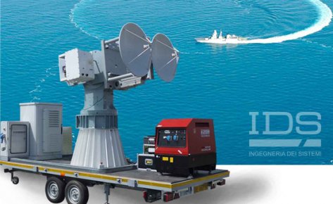
Dynamic RCS measurement
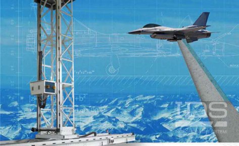
Static RCS measurement